MiSolarCasero.com


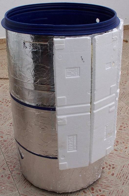
This complete assembly scheme is based on my construction project using the model 1 homemade solar collector and gravity tank.
In summary of this complete scheme, we will say that 2 water flows will circulate in the reservoir:
It is important to place a plastic mesh in the bottom, to maintain a reserve bottom for the water pump. We must ensure that the water pump always absorbs water, and never finds itself without the lack of it trying to pump air, because to begin with it is very bad for the pump itself, and because it requires a great effort to pass air to return To rescue the water, a bubble or air flow could stop the circuit until we manually purge the air from the pump-collector circuit.
We would be at that risk if we allow the fishing tube to have access to the bottom of the reservoir.
Placing this mesh as seen in the drawing (yellow mesh), we prevent the fishing tube from reaching the bottom, and in this way the water pump will always have a guaranteed water supply.
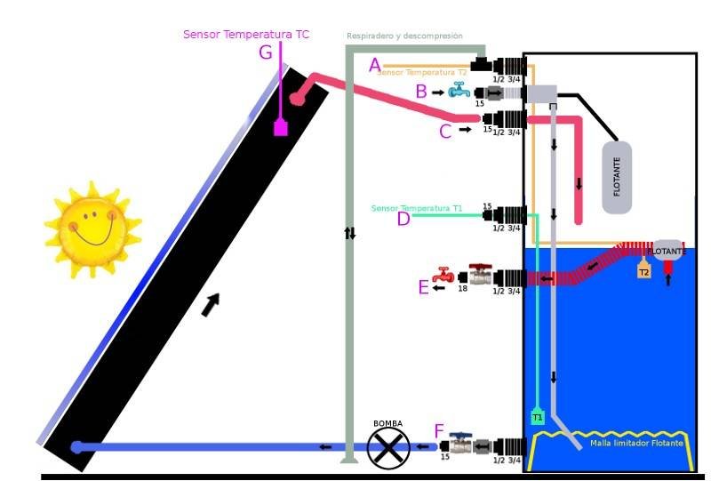
Below I describe the service of each connection of the deposit, which as you will see are labeled with a pink letter, naming them from top to bottom:
Connector 'A':
Connection with a tube that will allow the entry and exit of air as the water level rises or falls.
Never cover this tube, because when cold water enters it needs to push air out and if the air does not go out to the outside the tank could break or burst due to excess pressure.
It is advisable to connect a tube here, as the gray tube can be seen in the drawing, so that it appears somewhere where we can see the water fall, in case the mechanism that stops the filling fails, and the tank is flooded with nonstop water. (It does not matter how long this tube is, but it can never exceed the height of the tank itself)
This connection is made with a 'T' to connect to this vent and at the same time to a temperature sensor input.
This sensor is optional, it is equivalent to the reading of the water temperature at level (the water that will come out when the tap is opened) (if we are not going to put a sensor here, it will not be necessary to put the 'T')
(Sensor mounting is explained in the Temperature Sensors section)
Connector ‘B’:
Cold water inlet from the house to the tank, it has a little DIY because we have to couple a toilet tank filling mechanism and invent some way of vertical adjustment in the float to adjust to the level we want to fill the tank, preferably this level It can be adjusted to different levels without difficulty according to the needs and season of the weather.
We will attach a non-return valve (if possible) to force the water to flow into the tank, thus preventing any circumstance such as a leak or dismantling of the pipe from leaving all the water content. for that connection.
Because it can also happen that a very low pressure of the domestic water or a cut in the supply causes the water in the tank by gravity to want to compensate for the lack of flow or pressure in the cold water pipes.
If we do not put this valve, and we ever notice very hot water coming out of the cold water tap, this may be happening, that the tank is filling the cold water pipes by suction and gravity.
Connector ‘C’:
This connection is the one that takes the heated water from the collector to the interior of the tank, if possible in this connection and inside the tank we will extend it with a tube, to avoid the noise of the falling water flow.
Connector ‘D’ y Connector ‘G’:
These temperature sensors are optional, they are part of the management of a differential thermostat. Connector 'D' makes the reading of the coldest temperature of the tank (the lowest part), and Connector 'G' makes the reading of the hottest temperature of the solar collector, the thermostat compares the temperature of these two sensors and governs the water pump to exchange the waters at the right times.(Sensor mounting is explained in the Temperature Sensors section)
(If you cannot purchase a differential thermostat with its two sensors, you will have to adapt your system to the requirements of the thermosiphon system)
Connector ‘E’:
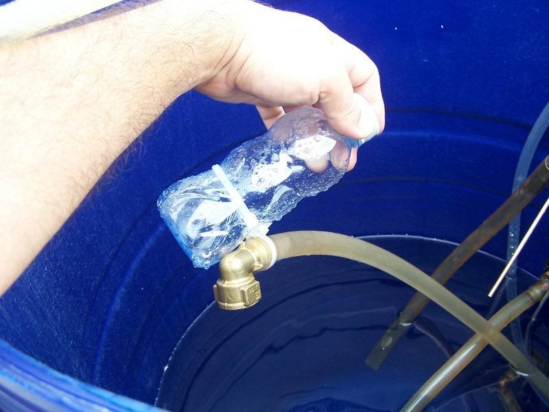
Inside this connection we have to connect a fishing tube (flexible tube) attached to a floating object: (I have put a vinyl tube, it is very good, flexible and withstands incredibly high temperatures)
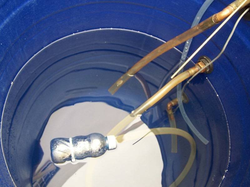
The need for this is because the water level in our tank is configurable, and because the water inlet and outlet work independently, then it is impossible to define an exact point to extract the water.
The intention of this is that said tube always supplies us with water and not air, as the level is variable and configurable, we have to pursue this level to 'suck' the water, and coincidentally the highest part is also the one that interests us because it is always the hottest.
If we have installed the sensor of the 'A' connector, said sensor must be attached to this hose, so that the reading is made on this variable level.
Outside of this connection a stopcock is necessary, because the leak or disconnection would cause the imminent emptying of the entire tank. But, although the drawing places this stopcock in the tank (it is an indicative drawing), it is not the best place, because in an emergency and we need to close this tap, we will not like having to run to the roof. The ideal is to install this stopcock in the most accessible place in the same tube, for example in the union of this tube to the pipes of the house
This connection will start to work after a first suction and the tubes that follow are filled with water, after this event the water will always come out automatically when you open any hot water tap, because the water that comes out of the tap and all the way it will go going down it will suck the water from this connection.
In the event that, for any reason, these tubes are emptied, we will have to manually apply that suction again, either from a tap, from the union of the tube of this connection with the house, or from the tank itself.
Connector ‘F’:
It is from where the water pump collects the water, collects it from the lowest part of the tank (the coldest area) and takes it to the beginning of the collector to be heated.
Here it is imperative to put a stopcock, because the breakage or leakage of the tube or some component of the collector would cause the emptying of the entire tank.
Here we put (if possible) a non-return valve or solenoid valve, for the possible dangers that I will comment on below
Pay special attention to the non-return valve of the ‘F’ connector (if you put it):
These valves usually come with an internal spring, and this spring requires a certain pressure to open in the correct direction and in my case the water pump did not deliver that "certain pressure" and the water simply did not circulate. It is very easy to check, before installing it we will take it by hand and blow in the correct direction as if imitating the flow of water.
If you notice that it does not open by blowing very lightly and you use a water pump with very little power, you may have problems here.
I recommend that when you have it installed you compare the flow rate with the valve on and without it.
If that is your case, that this valve slows down your recirculation, you will have to relieve that tension. It is simple, locate the spring from the inside, and take the tip of that spring outwards and you are pulling until you have extracted a small section, you cut it and return the tip of the spring to its place, and you go blowing and checking successively applying these small reductions of the spring until you consider a logical tension, but make sure that if there is a minimum tension and that when blowing in the opposite direction it does not allow air to pass. (That's how I did it and it was great).
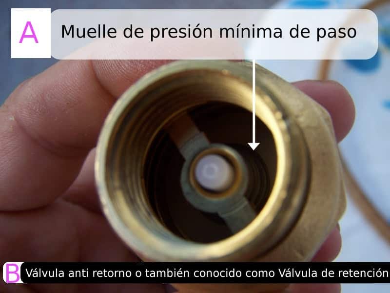
A - Minimum passage pressure spring
B - Non-return valve or also known as Check valve